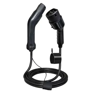
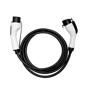
With the increasing number of electric vehicles, EV chargers have become as important to EVs as gas stations are to fuel-powered cars. An EV charger not only needs to provide stable charging for electric vehicles but must also ensure that the charging process is both safe and efficient. To achieve this, load testing of the EV charger is extremely critical. Today, we will discuss why EV charger load testing is important, how to conduct it, what to pay attention to in load design, and how to use advanced technology to enhance the performance and reliability of EV chargers.
The EV charger is the equipment used for charging electric vehicles. Its safety, reliability, and performance directly affect the user's charging experience and the safety of the vehicle. During the charging process, the EV charger must perform multiple tasks, such as detecting whether there is voltage in the charging circuit, determining the battery status, and sending charging commands through the CAN bus. If the charging circuit fails to detect voltage, the EV charger will alarm and stop working, which not only affects the user's charging schedule but may also damage the charger and the vehicle.
To ensure that the EV charger can operate stably under various conditions, load testing is indispensable. Through load testing, various scenarios in the actual use of the EV charger can be simulated to comprehensively test its performance, such as the stability of output voltage, current, and power, and its performance under different charging modes. In addition, load testing can identify potential problems in the design and manufacturing process of the EV charger, allowing for timely improvement and optimization, thereby enhancing the overall quality and reliability of the EV charger.
Currently, some EV charger manufacturers still use actual environment testing methods, in which the charger charges a matched battery to test performance. However, this method has several disadvantages:
Unable to monitor and determine in real time: During actual charging, it is difficult to monitor the overall operating status of the EV charger in real time and promptly detect potential problems.
Inaccurate test results: The actual testing environment is complex, making the results less precise and the process cumbersome.
Low testing efficiency: Real-world testing efficiency is low, making it difficult to repeat tests quickly, which limits both frequency and scope.
High cost: Real testing requires actual batteries and EV chargers, leading to high costs and additional losses during the testing process.
These limitations make traditional testing methods unable to meet modern EV chargers' requirements for high performance and high reliability. Therefore, it is crucial to develop a fast, accurate, and convenient testing method.
The EV charger testing load system provides an efficient, accurate, and convenient solution for charger testing. Through parallel connection, the charger testing load, EV charger, electronic load, and charging trigger are connected together. By setting the "charging voltage value" of the limited-voltage EV charger and selecting the CV mode, the charging voltage of the EV charger is used as the load parameter of the electronic load's CV mode to start the electronic load. After stable loading, the load functions as a stable voltage source capable of absorbing any current from the battery.
The control system sends a start signal via the CAN bus to start the EV charger. If the start is successful, the power of the electronic load will increase, and the control panel will directly display information such as the EV charger's output voltage, current, and power. If the charging start fails, the electronic load power remains unchanged, and the control panel data are all zero. This testing method can not only display and record electrical data in real time under different charging modes but can also comprehensively detect the charger's performance, including during fast charging, constant current, constant voltage, and constant power/constant voltage charging.
The advantage of the EV charger testing load system is that it can complete testing tasks quickly and accurately, greatly improving testing efficiency and result reliability. In addition, the system can be flexibly configured according to different testing needs to meet the requirements of various scenarios.
The design of high-performance EV charger loads is a core aspect of achieving efficient and safe charging for electric vehicles. Load design requires systematic planning from four dimensions: electrical performance, safety protection, protocol compatibility, and intelligent management.
The primary task of load design is to adapt to charging needs in various scenarios. In terms of electrical parameters, it should cover single-phase 220V and three-phase 380V voltage input, support mainstream power levels of 7kW, 11kW, and 22kW, and reserve scalability for future high-power requirements such as 43kW. Dynamic response must accurately simulate EV charging characteristics, including soft-start control during startup, power fluctuation response during charging (such as BMS requests to adjust current), and emergency stop mechanisms.
Safety redundancy is an indispensable part of load design. The load design must integrate multiple protection mechanisms such as overvoltage, overcurrent, leakage, and temperature protection to ensure that the circuit can be quickly cut off under abnormal conditions, preventing damage to the equipment or the vehicle. These safety measures effectively reduce potential risks during EV charger operation and ensure user safety.
The load circuit must balance steady-state and dynamic testing requirements. The resistive load module uses high-precision alloy resistors to achieve constant current simulation and must adopt air-cooling or liquid-cooling systems to handle long-term full-load operation. The dynamic load module relies on programmable electronic loads (PEL), using high-frequency switching devices (such as IGBT) to reproduce realistic charging waveforms and match inductance-capacitance networks to compensate for battery impedance characteristics, ensuring a power factor (PF) higher than 0.98.
EV chargers must support multiple national and international standard protocols to ensure broad compatibility. The Control Pilot (CP) circuit adjusts output power through PWM duty cycle, the Connection Confirmation (CC) signal monitors gun-to-vehicle connection status in real time, and the CAN bus exchanges key parameters such as SOC and voltage limits with the vehicle's BMS. The protocol layer must be compatible with GB/T 18487.1 (China), IEC 61851 (International), and ISO 15118 (Plug & Charge), and integrate OCPP 2.0 for remote start/stop, billing management, and other intelligent functions.
In terms of electrical safety, a graded protection strategy is adopted: the main circuit is equipped with circuit breakers for first-level overcurrent/short-circuit protection, and the control board integrates a high-sensitivity RCMU module to detect leakage currents below 30mA. Thermal management is achieved through temperature sensors that monitor hotspots such as IGBT and cable joints in real time, combined with intelligent-speed fans or liquid cooling to keep temperature rise within 50°C. The protection rating should reach IP54 (outdoor) or IP65 (dustproof and waterproof).
Traditional silicon-based IGBT/MOSFET devices have high switching losses, limiting system efficiency. Using silicon carbide (SiC) or gallium nitride (GaN) components can significantly reduce losses: SiC MOSFETs have a low on-resistance (only 1/10 that of silicon-based devices) and switching frequencies exceeding 100kHz, reducing switching losses by 30–50%; GaN devices have almost zero reverse recovery time, making them ideal for high-frequency PFC circuits, increasing system efficiency above 96%. Traditional hard-switching topologies achieve around 92% efficiency, while LLC resonant circuits use zero-voltage switching (ZVS) and zero-current switching (ZCS) to reduce switching loss below 1%, achieving over 95% efficiency. Bidirectional active power factor correction (PFC) circuits can improve the power factor (PF) to 0.99, reduce total harmonic distortion (THD) below 5%, and minimize grid pollution.
Based on feedback parameters such as SOC and temperature from the vehicle's BMS, the system dynamically adjusts output current. For example, when the battery approaches full charge, it automatically switches to trickle mode to prevent overcharge loss and reduce invalid energy consumption by 5–10%. Through built-in energy management algorithms, charging power automatically increases during grid off-peak periods (e.g., at night) to take advantage of lower electricity prices, reducing user costs while balancing grid load and improving energy utilization.
High-power EV chargers (such as 22kW) use modular designs, enabling or disabling modules as needed. During light load, redundant modules are shut down to reduce standby power consumption (<2W). With low-power MCUs and sensors, when no vehicle is connected, the system enters deep sleep mode, lowering energy consumption to below 0.5W.
The material fatigue of power electronic devices is the physical cause of aging. In IGBT modules operating at switching frequencies above 200Hz, silicon materials experience lattice distortion due to thermal stress, resulting in an annual increase in conduction resistance by 8–12%. The electrolyte drying phenomenon in electrolytic capacitors is even more pronounced, after 3,000 charge-discharge cycles, capacitance decay reaches 15%. Environmental factors and usage loads combine to accelerate aging; in southern humid regions, EV charger failure rates are 37% higher than in northern regions, and fast chargers have an average annual failure rate 2.8 times higher than slow chargers.
To address aging problems, impedance spectrum analysis-based component health assessment models can monitor power module aging status in real time. When the equivalent series resistance (ESR) of a module increases by 10%, the control system automatically adjusts the load current from 150A to 135A to achieve power chain stress balancing. Adaptive temperature control strategies build three-dimensional thermal field simulation models, activating gradient derating when ambient temperature exceeds 35°C. Through PWM modulation, the switching frequency is reduced from 20kHz to 16kHz, keeping the IGBT junction temperature within the safe limit of 125°C and reducing power loss by 18%. The battery SOC coupling control establishes a data channel between the vehicle's BMS and the EV charger. When the battery SOC reaches 80%, the system automatically switches to CV mode and linearly reduces the output current from 240A to 80A, protecting the battery and reducing the thermal load on the EV charger.
EV charger load testing is a key step in ensuring the safe and efficient operation of EV chargers. By adopting advanced testing load systems and load design, the performance of EV chargers can be comprehensively evaluated, improving their stability and reliability. At the same time, by understanding the mechanisms behind load aging and implementing effective countermeasures, the service life of EV chargers can be extended, and maintenance costs reduced. As the EV market continues to grow, EV charger technology will keep innovating and advancing. In the future, EV chargers will become more intelligent, efficient, and secure, providing EV users with higher-quality charging services. In the design, manufacturing, and maintenance of EV chargers, the importance of load testing cannot be overstated. Only through rigorous load testing can EV chargers operate stably under all working conditions, providing strong support for the widespread adoption and development of electric vehicles.


